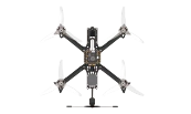
Nine steps. Most guides list them. This one explains why each sits where it does, because the order is what saves you from taking the aircraft apart again.
Every FPV build guide gives you roughly the same nine steps. Frame, motors, speed controllers, stack, wiring, receiver, binding. Follow any of them and you will end up with an aircraft.
What the lists rarely say is that the sequence is not arbitrary. Three or four of those steps are irreversible in practice — undoing them means desoldering joints you already made, or pulling apart a stack that is bolted under a board you have since wired. Get the order wrong and the cost is not confusion. It is an evening spent returning to where you were.
Here is the order, and the reason behind each position.
The frame comes first because everything else is measured against it. Arm spacing decides how long the motor wires need to be. The gap between standoffs decides whether your stack fits. The camera plate decides which camera size you can mount.
Build it fully — including standoffs and the top plate — then take the top plate off again. You want to have confirmed that it all goes together before you commit a single solder joint to it.
Motors go on while the frame is still bare and you can reach every screw from both sides. Once the stack is in, some of those screw heads are underneath it.
Two things matter here and they are easy to get wrong. Screw length: too long and the screw reaches into the motor windings, killing the motor the first time you spin it. Wire routing: the leads have to reach the ESC without crossing a propeller arc, and they should be secured before they can be cut by a spinning blade.
This is the first soldering step, and it happens while the ESC is loose in your hand rather than bolted into a stack. That is the whole reason it comes third.
The capacitor across the battery input is not optional decoration. It absorbs the voltage spikes that brushless motors throw back down the power leads — spikes that otherwise reach the flight controller and, over time, kill it. Fitting it later, after the stack is assembled, means soldering in a space the size of a coin with a board underneath you cannot afford to melt.
Do the XT60 leads here too. A battery connector soldered with the board free on the bench is a different job from the same connector soldered with the board mounted.
Now the two boards go together, separated by rubber grommets, bolted through the frame's standoffs.
The orientation of the flight controller decides everything downstream. The arrow on the board has to point forward, and "forward" has to match what you will later tell Betaflight. A stack mounted 90 degrees out will fly — badly, and in a direction you did not ask for — and you will not find out until step 7.
Three wires per motor, twelve joints. This is the step people rush and the step that produces the most failures, because a cold joint looks identical to a good one until the aircraft vibrates.
Order does not matter electrically — brushless motors will spin either direction depending on phase order, and you fix direction in software later. What matters is that each joint is solid and that no strand bridges to its neighbour.
Usually a single ribbon connector between the two boards. Quick, and easy to seat wrong. Check the pinout against both boards' documentation rather than assuming the plug only fits one way.
This is the step that justifies the whole order. Propellers off, battery on, motors spun individually from Betaflight's motor tab.
At this point you have a complete power path and nothing else. If a motor does not spin, the fault is in the last few steps and nowhere else — a solder joint, a connector, a dead ESC channel. You are debugging a system with four or five possible failure points.
Do this step after the receiver is connected and you are debugging a system with fifteen. That is the difference the order makes.
Two things to confirm here: every motor spins, and each spins the correct direction for its position. Direction is fixed in software, not by swapping wires — but you have to know it is wrong before you can fix it.
Only now does the control link enter the picture, and it enters a system you have already proven. Four wires typically: power, ground, and a UART pair.
Receiver protocol has to match your transmitter — a receiver of one protocol will not bind to a transmitter of another, regardless of what frequency both use. If you bought the two separately, verify this before you solder.
Binding pairs the receiver to your transmitter over the air. Then Betaflight has to be told what it is looking at: which UART the receiver is on, which protocol it speaks, which way the board is oriented, what your flight modes and arming switch do.
This is the longest step by far, and it is where a mechanically perfect aircraft becomes a flyable one. It is also where the earlier steps pay off or bite — an FC mounted backwards in step 4 surfaces here as an aircraft that rolls when you ask it to pitch.
The FPV system — camera, video transmitter, antenna — goes on after the aircraft itself works, because it is a separate path. Video has nothing to do with control, and mixing the two while debugging is how people lose an afternoon to a problem that was never where they were looking.
Then the finishing pieces: buzzer, GPS if you want it, and the tidying of wires that decides whether your first crash costs a propeller or a rebuild.
Read back through and the pattern is simple. Soldering happens while boards are loose. Testing happens at the smallest system that can be tested. The parts that are hard to reach get done before the parts that cover them.
Every one of those is a rule about undoing work, not about doing it. That is what a build order is for.
Where this comes from. The full build in FPV Drone Essentials runs from page 403 to 578 — the parts overview at 403, the nine steps across 422 to 538, then the analog and digital FPV systems at 540 and 552, and the finishing work at 568. Each step is photographed at the bench rather than described, which matters most at the soldering stages.
744 pages. Components, the full build photographed step by step, Betaflight configuration and flight training.
Buy on Amazon